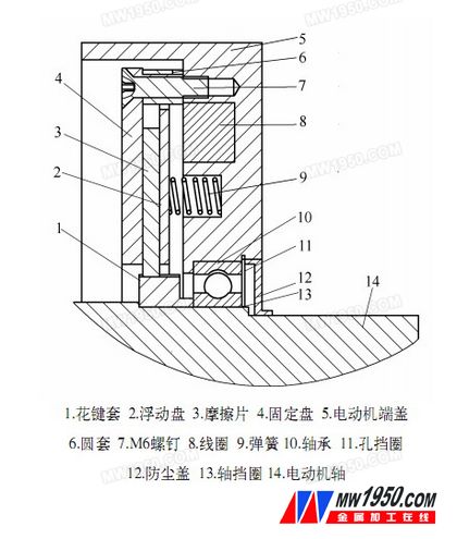
A KIA 630 horizontal machining center in Suzhou New District Jiguang Mould Manufacturing Co., Ltd. has recently suffered from a failure of the spindle to drop a distance after powering down or pressing the emergency stop switch. Because it is a horizontal machining center, the direction in which the spindle descends is the Y axis of the machine Tool. Based on past experience, it is initially determined that the brake of the Y-axis servo motor is partially broken. The motor model is FANUC a22/3000i. Since the horizontal addition is in the direction in which the Y-axis, that is, the spindle moves up and down, no weight or balance hydraulic cylinder is used, and the spindle motor and the gear box are estimated to have a weight of about 1 t, and all are pressed on the Y-axis screw to make the wire The bar produces a rotating action, and the brake system of the servo motor connected to the lead screw locks the screw to ensure that the spindle does not fall without the power supply. When the normal motor is energized, the power dropped by the main shaft is completely absorbed by the servo motor. Therefore, even when the Y-axis is stationary, the load on the Y-axis on the interface of the observation system can reach 50% to 60%. Several methods of setting the new mechanical zero point after motor repair are required before hands-on, which is described later in the article. First remove the three power cords of the motor. The thickest of these is the motor power cord, the encoder line is at the end, and a small plug near the shaft end is the brake power cord. Before starting to disassemble the motor, first use the wooden block to cushion the cast iron casing of the headstock inside the machine to prevent the spindle from falling when the motor and the screw are loose. The motor coupling adopts the German expansion sleeve type bellows coupling. The principle is similar to the spring clamp. When disassembling, first loosen the six M6 locking screws, and then use two M6 screws to open the expansion sleeve. It is possible to separate the coupling from the lead screw. However, due to the limited disassembly space, the wrench can only reach two locking screws at a time, so it is necessary to energize the motor multiple times during the disassembly, let the motor rotate at a suitable angle, and then adjust the underlay, which brings a lot of disassembly. big trouble. The servo motor is divided into upper, middle and lower sections, the end is the encoder and the tail cap, the middle section is the stator coil part, and the front part is the brake and the front end cover. Since the encoder is at the end of the motor and the housing is plastic, to avoid accidental damage during repair, the encoder must first be removed. The encoder is divided into upper and lower layers. The uppermost layer is the main body of the encoder. The optical and circuit parts are inside. Because it has nothing to do with this disassembly, it does not have to be opened. The end of the motor shaft can be seen by removing the screw on the lower layer of the encoder. Note that there is a cross-slider coupling and a copper pin connected to the circuit. The copper pin can be telescoped and connected to the corresponding copper contact in the encoder cover. Always take care not to damage the copper pins during maintenance. The next step is to remove the front end cover of the motor and first open the dust cover on the shaft end of the motor. The dust cover is somewhat like the cover of the milk powder can, but there is no turning edge and nowhere to start. Therefore, only use a destructive method to poke a small hole in the outer ring with a pointed Chisel, and then use a tool to pick up the dust cover. This will see the front bearing of the motor. Remove the circlip on the shaft, taking care not to remove the circlip of the outer ring. Loosen the four fixing screws of the front cover and remove the motor shaft from the front cover. This requires the use of a die or a tapping method, but it is not recommended. Because the entire motor is square and has no flanges, the three claws of the die are not used. Only one die ring can be made and fixed by the four screw holes of the motor flange. The three claws of the die grasp the die ring, and the top is placed in the center hole of the shaft head, so that the force can be applied. When starting to pull, because the front end cover of the motor and the stator housing of the motor have a layer of sealing glue, the force is very strong at the beginning, and once it is loosened, it is easy to separate. Then, the rear end cover is removed. The rear end cover does not need to be separated from the stator. Just hit the end of the motor shaft with a copper rod. When knocking, be careful not to hurt the cross slider. The entire rotor can be completely taken out. The rotor is made of permanent magnet steel, which is very magnetic. It should be placed properly after it is taken out to prevent a large amount of small chips from being adsorbed. Next, open the fixed disk and the entire brake part will be seen. The structure of the brake portion is as shown in the drawing. The brake system of the servo motor is of a power failure protection type, that is, when the servo motor is not energized, the floating disk 2 presses the friction plate 3 tightly against the fixed disk 4 under the thrust of the spring 9, and the friction plate 3 is the motor shaft 14 The spline sleeve 1 is fixed to the shaft by thermal expansion by means of a spline connection, so that the lead screw is no longer rotated. When the servo motor is energized, the control system also applies 24V DC to the brake coil 8 to make the coil magnetic. The floating disc is pulled to make the friction disc leave the fixed disc, the friction disappears, and the lead screw can be driven by the servo motor. Free to rotate. Observing the friction linings, it was found that because of the long use time, a layer of black carbon powder adhered to both sides of the friction lining, that is, this layer of carbon powder caused the braking force of the motor to be insufficient, and the spindle was dropped. So immediately clean up the toner and sand the friction plate and the fixed plate and the floating plate with sandpaper. Considering that the brake pads have some wear and tear, it is impossible to replace them. If it is not treated, the brake effect will still be unsatisfactory after being directly restored. It is very cumbersome to remove it. Because the entire motor disassembly and the process of combining the machine tool and the lead screw are particularly troublesome. In order to be able to install successfully, we thought of a method of cushioning the thickness of the copper under the 8 springs to compensate for the thickness. Because it is not known how much should be padded, if the pad is thick, the coil suction can not completely loosen the friction plate, so that the motor runs under load. If the pad is thin, the fault remains. Therefore, it is necessary to repeatedly energize the coil for testing, and gradually increase the thickness of the gasket from thin to thick. According to this maintenance experience, it is better to feel the gap between the friction plate and the fixed plate by 0.1mm in the energized state. When the coil is energized, you can connect a DC 24V switching power supply yourself. However, it should be noted that because this coil has a relatively large inductance, in order to prevent the reverse high voltage at the moment of the coil from being powered off, the diode can be reversely connected in parallel with a diode and a freewheeling circuit connected in series. At the beginning, we did not connect, causing a large spark at the moment when the power cord and the pile head of the coil were disconnected, but fortunately, the power supply was not damaged. The diode here only needs to find a common rectifier diode and a resistor with a higher power. After the gap is adjusted, the motor is fully restored. If the screw is not connected, the handle wheel magnification will be maximized, and the forward and reverse rotation will be fast. Observe that the motor load should fluctuate within 5%, which is normal. Finally, all of them are restored to the machine tool. After power-on, the motor load is increased by about 5% from the original 50% to 60% when the Y-axis is not moving, but it is still within a reasonable range. The last is to set the mechanical zero. The general zero recovery method is to return the zero point to the zero point before the motor is separated from the lead screw, and then make the corresponding mark on the appropriate sheet metal. At the time of recovery, the Y-axis is moved to the position where the mark is originally made by the hand wheel, and the Y-axis is set to zero by setting the system No. 1815 #4, and the specific method is not described in detail herein. Although this is very convenient, the new zero point and the original one are definitely not in the same position, which definitely affects the ATC tool change. On the other hand, because of the high precision of tooling exchange, we have all the parts that have been done once in order to improve the efficiency, and input the last machine coordinates directly in the system instead of manually correcting them. If the new zero point of the Y-axis is too different from the original, it means that all the part coordinates have to be adjusted. Therefore, the method we use is to press a ring gauge on the tool before removing the motor, use the table to find the center of the ring gauge, and record the mechanical coordinate value of this point. When the Y axis is recalibrated to the center of the ring gauge during recovery, the value recorded is moved to the zero point, and the Y axis is set to zero at that position. You can also find a suitable part instead of a ring gauge. The zero point restored by this method is very high, and all workpiece coordinates and ATC tool change positions do not have to be adjusted again.
The three-point wood drill is a variant of the twist drill, because the conventional twist drill is easy to deviate when drilling on a flat processing surface. When drilling metal, a pilot hole is usually drilled to locate the Drill Bit. But when doing woodworking, we can have a more convenient choice. The straight tip of the three-point woodworking drill is nailed into the wood like an awl to ensure that the drill will not slip.
Wood Working Bits are cutting tools used to remove material to create different kinds of holes in wood materials. In order to create holes drill bits are usually attached to a drill, which powers them to cut through the objects.
Wood working drill Machining accuracy is good, and drilling out of the hole cleanliness is good, small burr, Wood Working Dril,Wood Drill,Cutting Tool,Metal Cutting Behappy Crafts (suzhou)Co.,Ltd , https://www.haoyuebehappy.com The role of the brake
2. The process of separating the motor from the lead screw
3. Structure with brake servo motor
4. Structure of the brake part
5. Brake adjustment and motor load judgment
6. Zero setting
