The controller is an important part of the photovoltaic power plant. When designing and selecting the controller, it must be considered whether the controller can optimize the control and management of the photovoltaic power plant's power conversion and battery charging. Only by selecting a suitable type can we improve the safety and reliability of photovoltaic power plants and provide users with better power quality. Stand-alone photovoltaic power plants usually consist of photovoltaic arrays, battery packs, controllers, inverters, low-voltage transmission lines, and user loads. The battery functions as a storage box to regulate the electric energy: when the sunlight is sufficient, the battery generates excess energy; the battery group stores excess electric energy; when the system generates insufficient power or the load power is large, the battery pack supplements the electric energy to the load. And maintain the stability of the supply voltage. The controller is the control part of the photovoltaic power plant: it continuously switches and adjusts the working state of the battery pack according to the change of the sunshine intensity and the load, so that it can be alternately operated under various operating conditions such as charging, discharging or float charging. In order to ensure the continuity and stability of the work of the photovoltaic power plant, the battery group can continue to charge, stop charging, continue to discharge, reduce the amount of discharge or stop discharging by detecting the state of charge of the battery pack, protecting the battery pack from over-charging and Discharge; In addition, the controller also has a variety of protection and monitoring functions, the controller is the backbone of the entire power plant, its operating conditions directly affect the reliability of the entire plant, is the key to the system design, production and installation process need special attention section. Controller controls the basic principle of charge and discharge 1 battery charge control Different batteries have different charge and discharge characteristics, so different control strategies are also required. The lead-acid battery is taken as an example to illustrate the working principle of the controller. Lead-acid batteries have a variety of charging methods, such as float charging, current limiting constant voltage charging, and incremental voltage charging. The most commonly used is current-limited constant-voltage charging. The change in the terminal voltage of the battery during charging is shown on the left side of the figure below. The charging process is divided into three phases. In the first stage, the sulfuric acid formed in the micropores of the active material swells too late to diffuse outside the plate, so the battery potential increases, the battery terminal voltage rises faster (OA section), and the second stage, with the active material microwell The increase in the proportion of sulfuric acid in proportion to the speed of out-diffusion gradually tends to balance, so the battery terminal voltage rises slowly (AB segment); in the third phase, the current causes a large amount of water in the battery to decompose, starting to produce a large number of Gas, these gases are poor conductors and can increase the internal resistance of the battery, the battery terminal voltage continues to rise but the speed of the rise is significantly slower (CD segment). After the third stage, if the battery continues to be charged, it will be damaged due to overcharging, affecting the service life of the battery. According to this principle, a voltage measurement and voltage comparison circuit is set in the controller. By monitoring the voltage value of point D, it can be judged whether the battery should end charging; this control method is voltage type charging control, and the comparator setting is D. Point voltage is called "threshold voltage" or voltage threshold. 2 basic principles of battery discharge control The right side of the figure shows the discharge process of lead-acid batteries. Similar to the charging process, the terminal voltage of the battery during discharge is also composed of three stages. In the first phase, when the discharge begins, the voltage at the battery terminal rapidly drops (OA segment); in the second phase, the voltage at the battery terminal slowly decreases (AC segment); in the third phase, the terminal voltage of the battery is fast in a very short time Reduce (CD segment). It can be seen that the longer the second stage of the discharge process, the higher the average voltage and the better its voltage characteristics. According to this principle, a voltage measurement and voltage comparison circuit is set in the controller. By detecting the voltage value at point D, it can be judged whether or not the battery should end the discharge. This control method is the voltage type discharge control, and the voltage at point D is called " Threshold Voltage or Voltage Threshold. Controller type and characteristics At present, the commonly used photovoltaic system charge and discharge controllers have multiple series-bypass and pulse-type multiple types, each of which has its own characteristics and application objects are not the same. 1 series controller The controller detection circuit monitors the battery terminal voltage. When the battery is fully charged and the voltage reaches the corresponding threshold, the series controller switching element cuts off the battery charging circuit and the battery stops charging; when the battery terminal voltage drops to the voltage threshold for restoring charging, The switching element switches on the battery charging circuit and restores the battery charge. The advantage of the series controller is its small size, simple circuit, and low price. However, due to the tube voltage drop in the control power transistor, a large energy loss occurs when the charging voltage is low. In addition, when the control element is disconnected, the input voltage will rise to the level of the open circuit voltage of the power generation unit, so the series controller is suitable for photovoltaic power generation systems below the kilowatt level. 2 bypass controller The controller monitoring circuit monitors the battery terminal voltage. When the battery is fully charged and the voltage reaches the corresponding threshold, the switching element turns on the energy-consuming load and disconnects the battery circuit. The over-charge current will be transferred to the energy-consuming load by the switching element and will be redundant. The power is transformed into heat energy. When the voltage at the battery terminal drops to the voltage threshold at which the charging is resumed, the switching element disconnects the energy-consuming load and simultaneously turns on the battery charging circuit. The bypass controller is simple in design, inexpensive, and has a low loss in the charging circuit, but requires a large current-switching capability of the control element. The simple bypass controller is mainly used in photovoltaic power generation systems below the kilowatt level, and high-standard bypass controllers can also be used for higher power photovoltaic power plants. In a matrix of multiple solar panels connected in series, the adjustment of the battery charging voltage by bypassing one or more panels in the series group is called partial bypass control. The circuit principle of some bypass controllers is shown in the figure below. Show. 3 multi-level controller The core component of the multi-stage controller multi-circuit is a charge signal generator controlled by the charging voltage. Multi-stage controller according to the state of charge of the battery, the controller automatically sets a different charge current: When the battery is not full, allow the simulation of all the current flow into the battery pack; When the battery is nearly full, the controller consumes some The output power of the guideline in order to reduce the current flowing into the battery; when the battery pack gradually approaches full fill, the "turbulent" charge gradually stops. Applying the multi-stage controller principle to a photovoltaic power plant composed of a plurality of sub-arrays can form a multi-path control, and no current generated by one sub-matrix becomes a multi-step controlled charging current ladder. According to the state of charge of the battery pack, the controller turns on the input of each sub-matrix in turn, and can also switch the input of each sub-matrix one by one to the energy-consuming load, thus generating different charging currents of different sizes. As shown below. In order to make full use of solar energy, surplus power of the sub-matrix can also be transferred to the secondary power load. 4-pulse controller The core component of the pulse controller is a charge pulse generator that is modulated by the charging voltage. The controller operates in a chopping mode to pulse the battery. When the charging starts, the pulse controller charges with a pulse width, and as the charging voltage increases, the charging pulse width gradually narrows and the average charging current also gradually decreases. When the charging voltage reaches a preset level, the charging pulse width becomes 0, charging termination. The pulse controller has reasonable charging mode and high efficiency, and is suitable for use in photovoltaic power stations with large power. The basic principle of pulse width modulation (PWM) controller and pulse controller is the same. The main difference is that the charging pulse generator is designed as a pulse width modulator so that the instantaneous change of the average charging current of the charging pulse more closely matches the current state of charge of the battery. The most ideal state of charge is to comply with the charge current of the battery. The AC-DC converter PWM controller can also achieve the maximum power tracking function of the PV power plant. Therefore, pulse width modulators can be used in large-scale photovoltaic power plants. The disadvantage is that the PWM controller itself will bring about certain losses (about 4%~8%). This basin mixer tap has hot and cold water to choose temperature as you like. Bathroom Wash Basin Faucet use high quality brass material in basin mixer tap which meet the European requirement . The basin faucet have protection against water block. The life time of switch is 500,000 times. Widespread Bathroom Faucet,Widespread Bathroom Faucet Bronze,Three Hole Sink Faucet Bathroom,Bathroom Sink Faucets HESHAN CAIZUN SANITRAYWARE CO.,LTD , https://www.caizunbathroom.com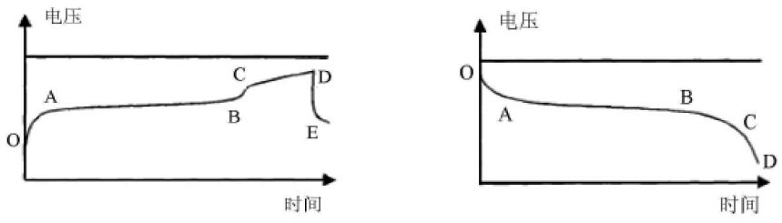
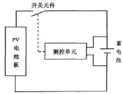
Series controller 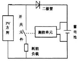
Bypass controller 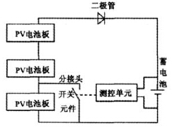
Partial bypass controller 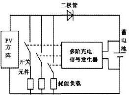
Multi-stage controller 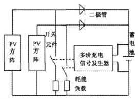
Multi-level controllers with different current levels 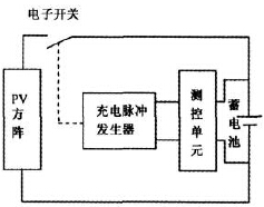
Pulse controller