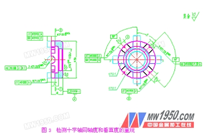
How to detect the position of the cross shaft? It has been mentioned that the position degree of the part is composed of verticality, coaxiality and coplanarity, and the three items can be detected separately. The gauge form is shown in Fig. 3. In Fig. 3, the unopened gap on the cross recess is in the gauge "L", and the gap is "LB (standby gauge)". The detection method is: the coaxial groove in the same axial direction detects the coaxial of the cross shaft. Degree, two mutually orthogonal holes detect the perpendicularity of the cross shaft. If the coaxiality and verticality of the cross shaft are both qualified, it cannot be said that the axis position of the cross shaft is correct because the X-axis and the Y-axis are Coplanarity is not known, so it must be tested. The detection gauge for detecting whether the X-direction and the Y-axis are in the same plane is shown in FIG. The detection method is as follows: the cross shaft is placed in the cross recess, so that the head of the dial indicator is in contact with the highest prime line of any axis on the cross shaft of Φ27s6 (+0.048 +0.035), and the hand wheel is rotated to rotate the disc 180°. , the difference δ between the maximum indication values ​​on the dialometer 1 and the table 2 is the coplanarity error of the X axis and the Y axis of the cross axis. If the error is in the range of 0.08 mm, the axis X of the cross axis is Y is coplanar with respect to the axis, otherwise it is not coplanar (the amount of variation in the size of the quadrilateral diameter is extremely small, and it can be considered that the influence of the dimensional variation is 0 in the error configuration of the coplanarity). 3 Planetary wheel's critical project analysis and detection method The back of the planet wheel is a convex spherical surface that cooperates with the concave spherical surface of the differential case. If the spherical shape of the spherical surface of the planetary gear is not correct, it will affect its "fit" with the concave spherical surface of the differential, resulting in differential speed. The operation of the device is blocked, the friction is aggravated, and the concave spherical surface of the differential case is prematurely worn and fails (the differential case is quenched and tempered, HRC38-42, the planetary wheel is quenching hardness, HRC60-64), and the wheel Gear accuracy is also an important item, and the test methods are not discussed in this paper. For the convex spherical surface R of the planetary gear and its positioning dimension L, we use the spherical gauge L-1T (pass gauge) and L-1Z (stop gauge) to detect the R value, and compare the positioning dimension L by comparison method, see Figure 5a and Figure 5b. After the workpiece is geared, the ring gear is positioned, the spherical surface of the fine car R, the size of the spherical surface on the process diagram SR=68-0.06 -0.12 is detected by the R gauge shown in Fig. 5a, and the positioning dimension L=68 0 -0.05 Tested by the method shown in Figure 5b, the steps are: first adjust the dial indicator with a standard gear (commonly known as the sample wheel), remove the standard gear, and replace it with the workpiece to be inspected. The difference between the indications on the dial indicator is the positioning size. The deviation of L, if the deviation is within 0?0.05, the positioning dimension L of the workpiece is qualified. In the process of finishing the spherical surface, the coaxiality between the center of the spherical surface and the center of the gear is expressed by the radial runout of the spherical surface (the amount of runout δr = 0.05). Figure 5b is also one of the methods for detecting whether the center of the spherical surface R is coaxial with the center of the gear. The dial indicator head is in contact with the spherical surface of the workpiece, and the workpiece is gently pressed by hand to fit the concave spherical surface of the base, and the workpiece is rotated. One week, if the measured value is not more than 0.05, the coaxiality of the center of the spherical surface R and the center of the gear is acceptable. In the figure, R ZJ = 66.05 is the taper distance. Figure 5c shows the method of detecting the coaxiality error between the center of the planetary surface SR and the center of the gear by the mandrel positioning on the yaw tester: rotating the workpiece one revolution, the difference between the indications on the dial indicator is the spherical surface. The coaxiality error between the center of the SR and the center of the gear. Waste Bottle Trap,Brass Bottle Trap, Bottle Trap Jiangmen Yunspire Sanitary Ware Hardware Industry Co., Ltd. , https://www.yunspirefaucet.com
Previous Next