1 Introduction Figure 1 Frame composition and frame decomposition scheme In addition, it is necessary to consider the pre-spot welding of the parts, the welding speed of the robot, the welding time distribution of the welds, the starting and closing times, and the interference between the jigs and the robot and the jig. After calculation, drawing inspection and planning, the operation content is divided into four steps: supervisor pre-spot welding, supervisor finished welding, frame pre-spot welding, frame complete welding, and correspondingly four robot welding stations are set up. Figure 2 Overall layout of the motorcycle frame robot welding production line Analysis of the frame structure, obviously from the combination of the main elbow and the fuel tank is a better solution, as shown in Figure 1b. That is to say, the parts 1, 2, 3, 4, 5 and 6 are first welded together, and then welded to parts 7, 8, 9 and 10. Figure 3 Typical configuration of the robot welding station Next page
Full Spectrum Led Grow Light Bar 800w with 10pcs bar, samsung chip and meanwell driver works well for succulents, indoor plant grow light, grow light bulbs for plants. Can customized spectrum by your requirement.
4/6/8/10/12 bars available.
OEM:
package customized, MOQ 200pcs
Logo customzied, MOQ 50pcs
Spectrum customized, MOQ 100pcs
(Can be negotiated)
Waterproof Led Grow Light Bar,System Led Grow Light ,Agriculture Systems Led Grow Light ,Led Grow Light Complete Kit Shenzhen Wenyi Lighting Technology Co., Ltd , https://www.wygrows.com
Industrial robots not only improve production efficiency, but also greatly improve product quality, so they are widely used in the field of welding. This paper introduces the composition and main technology of this type of workstation through the example of motorcycle welding.
The motorcycle frame is made of some loose parts welded. Some parts have been welded to a certain shape in the previous process and treated as a part when the final frame assembly is welded. The frame parts are shown in Figure 1a. These parts must be positioned and clamped one by one on the fixture, and there is no interference between the fixture and the fixture, and it is easy to weld. It can be seen that it is quite difficult to clamp the frame with one position, and it should be divided into blocks. 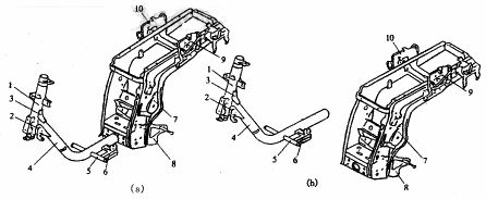
(a) Schematic diagram of the frame structure (b) Frame decomposition scheme
2. Overall layout
Before you can make a master plan, you should do three things first:
(1) Estimation of the specific dimensions of the clip. Analyze the positioning and clamping scheme of each part and leave a certain room to estimate the shape and size of the clip. If necessary, use it as a graph estimation.
(2) Determine the basic form of the positioner. The workpiece clamp should be able to change position so that the welds around the workpiece can adapt to the possible welding gun posture of the robot; in addition, in order to give full play to the working ability of the robot, the loading and unloading time of the workpiece should be as close as possible to the working time of the robot. It is preferable to provide two sets of clamp devices that can be exchanged with respect to the robot.
(3) According to the weight and work space, the robot model is selected.
For the specific operation content of a certain workpiece, with the change of the number of robots used, the investment of the factory, the degree of automation, the operation mode, the layout of the workshop equipment, the logistics method and the technical level of the designer, multiple sets of overalls can be formed. The design plan, after careful analysis and research, repeated comparisons, finally preferred a set of practical and feasible solutions. For the motorcycle frame welding operation, in the actual design, a total of five options are made. Starting from the degree of automation, cost, productivity and user opinion, the final selected overall layout is shown in Figure 2. 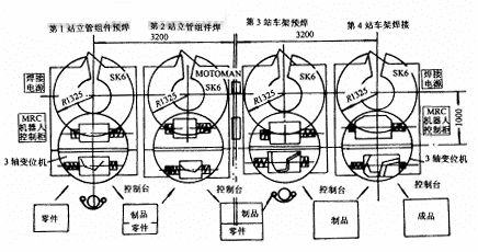
There are four workstations in the overall layout. The first and third workstations are all spot welding of the robot, and the second and fourth workstations are the finished welding of the main assembly and the frame assembly. Each workstation uses a 3-DOF turntable, which is divided into two working positions. When the robot is working in the inner working position, the workpiece can be manually loaded and unloaded and set on the outside.
In addition to the robot body, positioner and fixture, the workstation has welding power supply, protective gas system, wire feeding system and control system. The typical configuration is shown in Figure 3. The positive and negative poles of the welding power source are respectively connected to the welding wire and the positioner body through wires; the wire feeding motor is generally mounted on the robot body, and the wire disc and the wire barrel are mounted on a shelf or placed on the ground; the protective gas pipe is passed through a special joint. Connected to the wire feeder; the robot control box and the electric control box jointly control the coordination of the entire workstation. 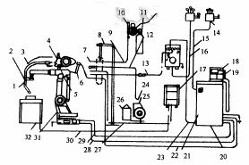
1. Collision sensor device 2. Welding torch 3. Welding gun conduit 4. Wire feeding device 5. Motor frame
6. Catheter support 7. Connector 8. Wire tube rotating bracket 9. Protection air tube 10. Pressure gauge
11. Protective gas cylinder 12. Wire feeding tube 13. Control wire 14. Air switch 15, 16. Power cord 17. Welder 18. Display 19. Teaching box 20. Robot control cabinet 21. Control cabinet door 22. Collision sensor Wire 23. Integrated wire 24. Connector 25. Wire tray 26. Wire drum 27. Welding positive wire 28, 29. Power cable 30. Soldering negative wire 31. SK6 robot 32. Positioner 
