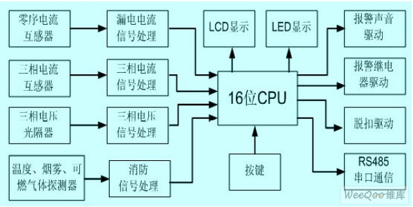
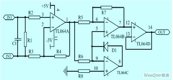
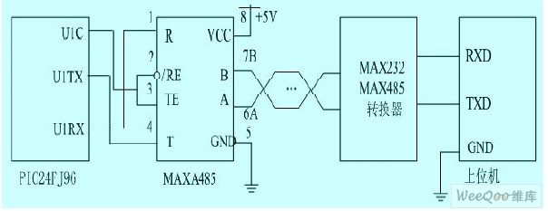
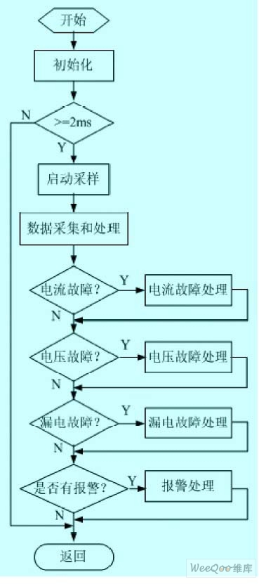
1 Introduction In recent years, national fire accidents have shown an upward trend. In fire accidents, the proportion of electrical fires remains high, accounting for 27% of the annual fire occurrences, and losses account for 52% of fire losses. The annual casualties and property caused by fires The loss is huge, and the task of preventing and effectively curbing electrical fires is imminent. Relevant national departments have successively formulated or revised relevant standards and regulations, and required to set up an electrical fire monitoring and alarm system in the building. According to the new standard of electrical fire monitoring system (GB14827-2005), this paper designs an intelligent residual current electrical fire monitoring detector, which can be used alone or through the RS485 bus to connect with electrical fire monitoring equipment. Complete electrical fire monitoring system. 2 Design basis for electrical fire monitoring detectors 2.1 Detector related standards The designed device shall comply with the "Electrical Fire Monitoring System" (GB 14287-2005), "Residual Current Electric Fire Monitoring and Alarming Device" (GB14287.2-2005), "Code for Designing Building Fire Protection" (GB 50096-2006), Standards for fire protection design of high-rise civil buildings (GB 50045-2005), "Building electrical fire prevention requirements and testing methods" and "Installation and operation of residual current action protection devices" (GB13955-2005). 2.2 Introduction to Electrical Fire Monitoring System The electrical fire monitoring system is composed of electrical fire monitoring equipment and electrical fire monitoring detectors. The system should meet the requirements of the Electrical Fire Monitoring System (GB 14287-2005). When the detected parameter in the protected line exceeds the alarm set value, the electrical fire monitoring system can issue an alarm signal, a control signal, and can indicate the alarm location. The electrical fire monitoring equipment can receive alarm signals from electrical fire monitoring detectors, emit sound and light alarm signals and control signals, indicate alarm parts, record and save alarm information. The residual current type electrical fire monitoring detector can detect changes in electrical fire hazard parameters such as residual current and temperature in the protected line. It can be divided into two types according to the working mode: one is a stand-alone detector (a detector with monitoring alarm function) Second, non-independent detectors. This paper designs a smart stand-alone detector. 2.3 Causes of residual current Under normal circumstances, when there is no equipment leakage or ground fault in the circuit, as shown in Figure 1, according to the circuit principle, the current phasor sum of the three-phase four-wire power supply is equal to zero, that is, Ia+Ib+Ic+In=0. The vector sum of the magnetic fluxes generated in the current transformer is equal to zero. At this time, the induced current IL=0 in the secondary coil, so the line is normally supplied with power. When equipment leakage or fault grounding occurs in the circuit, such as the fault leakage current ZI, the current phasor sum of the three-phase four-wire power supply will not equal zero, ie Ia+Ib+Ic+In ≠0, which is generated in the current transformer. The vector sum of the magnetic flux is also not equal to zero. At this time, there is an induced current in the secondary coil, that is, the residual current IL≠0. Figure 1 shows the working principle of the residual current transformer. 2.4 The necessity of setting up an electrical fire detector Arc-to-ground short-circuit in electrical ground faults is an important cause of electrical fires. The arc-to-ground short circuit has a large impedance and voltage drop, which limits the fault current, makes the overcurrent protector unable to operate or can not act in time to cut off the power supply, and the local high temperature generated by the leakage arc of several hundred milliamperes can reach 2000. Above °C, enough to ignite the surrounding combustibles and cause a fire. Moreover, electrical equipment is distributed in all corners of buildings, and the scope of damage is wide. If the leakage of the system is not monitored and prevented, it will pose a threat to personal and property safety, and there is a great fire hazard. The residual current type electrical fire monitoring detector can accurately monitor the fault and abnormal state of the electric line, and can effectively prevent the electrical fire accident of the building caused by the grounding arc caused by the leakage. In order to ensure the safety of people's lives and property, it is necessary to install residual current electrical fire monitoring detectors at the power inlet and trunk lines of buildings. 3 detector design 3.1 Basic system functions The intelligent residual current type electrical fire monitoring detector integrates monitoring, analysis, alarm and control of electrical faults such as residual current, short circuit, overload, overvoltage and undervoltage (phase loss). Mainly has the following features: (1) It has leakage current, long overcurrent delay, short overcurrent delay and short circuit transient protection to form the required protection characteristics. Intelligent setting of leakage current, overcurrent long delay, overcurrent short delay and overcurrent transient setting and warning value. In addition, it also has an overvoltage alarm function and a phase loss alarm function. (2) Display and store the line address, fault type, fault occurrence time, leakage current, and three-phase current value of the fault occurrence point. Up to 1000 historical faults can be recorded and saved for long periods of time until they are deleted with instructions. (3) Using RS485 bus communication technology, the bus and the host can be used to form a master-slave monitoring system to realize user network connection. On one computer, 1 to 250 intelligent detectors can be remotely monitored online, and each user can be inspected at any time. In the case of electricity, the power supply lines of each user can be switched on or off at any time. (4) With pre-alarm function, when the action parameters are approached, the humanized intelligent control strategy of early warning and over-standard alarm tripping, with advanced active protection mode, intelligent control structure, data recording and control of power running line safety status And can remotely implement the circuit breaker trip of the specified node. (5) It can be connected with temperature probe, smoke detector, flammable gas detector, etc., and linkage with the automatic fire alarm system center to remotely cut off the load power supply, and DC12V signal feedback to the alarm center to trigger the alarm. 3.2 Overall hardware design The residual current type electrical fire monitoring detector is mainly composed of power supply, single chip microcomputer PIC24FJ96, three-phase alternating current voltage and current detecting circuit, residual current detecting circuit, RS485 communication module, alarm, button and display, etc., as shown in Figure 2. Figure 2 Detector block diagram. Its main working principle: after the three-phase current, leakage and voltage signals obtained from the current transformer and the linear optical isolator are conditioned, input to the A/D conversion of the single-chip microcomputer, and the single-chip microcomputer samples it and analyzes it, and outputs the corresponding Display and alarm signals, etc. The result of the analysis can also be transmitted to the host computer via the RS485 bus. 3.2.1 Single-chip circuit The microcontroller uses PIC24FJ96, which is a high-performance CPU of improved Harvard architecture designed by Microchip. It is the core of the detector. It performs various control functions of the detector, including three-phase voltage, three-phase current and leakage current. Sampling, data processing, alarm output, communication with the host computer, LCD display and buttons. 3.2.2 Residual current detection circuit The residual current detection circuit is a zero sequence current transformer. The protected phase line and neutral line pass through the toroidal core, forming the primary coil of the transformer. The winding wound on the toroidal core forms the secondary coil of the transformer. If no leakage occurs, then the phase line flows. The current vector sum of the neutral line is equal to zero, so the corresponding induced electromotive force cannot be generated on the secondary coil. If a leakage occurs, the current vector of the phase and neutral lines and unequal to zero cause an induced electromotive force on the secondary coil. This signal is sent to the intermediate link for further processing, as shown in Figure 3. Figure 3 Residual current detection circuit. The processed signal is sent to the MCU, and the MCU samples 20 points per cycle. According to Equation (1), the effective value of the residual current can be calculated. Where X is the sampled value. 3.2.3 Three-phase voltage and current detection The voltage detection consists of a linear optical isolator, an operational amplifier, and a rectifying and filtering circuit. Since the detector does not require high voltage accuracy, the use of a light spacer can greatly reduce the size of the system. Current detection consists of a three-phase AC transformer, an operational amplifier, and a rectification filter circuit. The three-phase AC transformer converts the current into a voltage signal, and the circuit formed by the operational amplifier is conditioned and rectified and input to the A/D converter of the single chip microcomputer for conversion. 3.2.4 RS485 bus hardware circuit Figure 4 RS485 bus hardware circuit. The detector communicates with the host computer using RS485 bus. One host can control up to 250 detectors. The RS485 communication system adopts a master-slave structure. The slave does not actively send commands or data, and everything is controlled by the host. Therefore, in a communication system, only one upper computer is used as the host, and the other slaves cannot communicate with each other, and even if there is information exchange, it must be forwarded through the host. The hardware circuit for communication with the host computer is shown in Figure 4. Figure 4 RS485 bus hardware circuit. 4 detector software design The software completes the function of the whole detector, adopts the modular structured C language programming scheme, and the C language has the advantages of high code generation quality, high program execution efficiency and good portability. The software part includes voltage, current and leakage sampling, data processing, alarm output, key input and liquid crystal display. The system block diagram of the software is shown in Figure 5: Figure 5 Software system block diagram. Residual current detection alarm judgment is an important part of software design. It analyzes, compares, judges and converts A/D converted data into corresponding subroutines. If the detected residual current value is less than the set value but greater than 0.8 times the set value, the detector will alert the person on duty in the form of an audible and visual alarm. If the residual current is greater than the set value, the detector continuously detects the residual current to prevent interference, and trips after the set time has elapsed. Modbus communication protocol is adopted between the host computer and the host computer. The Modbus communication protocol is one of the mainstream communication protocols commonly used by international intelligent instruments. When the host computer sends a communication command to the probe, the slave device that meets the corresponding address code receives the communication command, and reads the information according to the function code and related requirements. If the CRC is correct, the corresponding task is executed and the execution result is returned to the host. The returned information includes the address code, function code, executed data, and CRC check code. If the CRC check fails, no information is returned. 5 Conclusion The intelligent design of the residual current electrical fire detector is realized by using single-chip microcomputer, and the combination and intelligentization of the traditional circuit breaker function are realized, and the systemization and networking of the circuit breaker control can be realized through the application of the bus communication technology. After the actual work test, the residual current type electrical fire detector in this paper achieved the intended purpose and passed the national fire electronic quality inspection. Medium Duty wheels,Nylon Caster With Brake,Medium Nylon Caster Wheels,Polyurethane Caster Wheels BENYU CASTERS & WHEELS CO.,LTD , https://www.benyucaster.com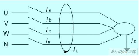

:
Design of Intelligent Residual Current Electric Fire Monitoring Detector
5 times
Window._bd_share_config = { "common": { "bdSnsKey": {}, "bdText": "", "bdMini": "2", "bdMiniList": false, "bdPic": "", "bdStyle": " 0", "bdSize": "24" }, "share": {}, "image": { "viewList": ["qzone", "tsina", "tqq", "renren", "weixin"], "viewText": "Share to:", "viewSize": "16" }, "selectShare": { "bdContainerClass": null, "bdSelectMiniList": ["qzone", "tsina", "tqq", "renren" , "weixin"] } }; with (document) 0[(getElementsByTagName('head')[0] || body).appendChild(createElement('script')).src = 'http://bdimg.share. Baidu.com/static/api/js/share.js?v=89860593.js?cdnversion=' + ~(-new Date() / 36e5)];