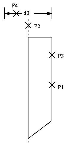
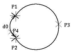
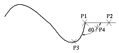
Length of the line segment: Select the line segment with the left button, and then use the middle button to calibrate the position where the size parameter is to be placed. Radius of a circle or arc: Select a circle or arc and specify the appropriate position. Circle on the plane: Select the circle with the left button twice and then position the position with the middle button The angle of the arc: first select the end points of the arc, then select any point in the arc, then specify the position. Distance between two parallel lines: Select two parallel lines and then calibrate the position where the size parameters are to be placed. The distance between a graphic unit and the centerline: Select the unit and centerline, and then specify the appropriate location. Select the two ends of the curve and mark the horizontal or vertical distance between the two ends. Steps to read the punctuation file and create an irregular curve: Then use the left button to select the coordinate to be referenced, and then press the middle button to complete the establishment of the reference relationship. Select " Modify " and select the irregular curve. Select " Regenerate " to complete the reading of the coordinate points. The user can also use the " Save Pnts " command to archive the data points of the irregular curve. The data format is as follows: Angle of the end point of the irregular curve: first select the end point of the irregular curve, then select the reference geometry of the angle to be marked, then select the curve body, and finally specify the angular position. Construction Laser Rangefinder Construction Laser Rangefinder,Sport Rangefinder,Distance Rangefinder,Obstruction Mapping Rangefinder Rxiry (Jiangsu) Optoelectronic Co., Ltd , https://www.rxiryrangefinder.com
Figure 2.1: Standard method for vertical cylinder dimensions 
Figure 2.2: The method of arc angle 
Figure 2.3: Angle of the endpoint of the irregular curve
Pro/E comprehensive skills tutorial: dimensioning skills (Figure)
After the section is completed, start to set the dimension parameters of each geometry. First, select the unit to be set with the left button, and then use the middle button to calibrate the position of the dimension parameter. The following describes the calibration methods for various types of parameters.